
The OHMIFUCKINGGAWD: OhMiBod Repackaged
My god. I did something. I actually did something.
I don't know if anyone realizes this, but I haven't really built anything in the last 18 months. Twitterdildonics was two hours of me sitting on a couch cutting and pasting code together. Well, and really, this is just me cutting and pasting parts together, but still, it's something, and it's a gateway to more somethings.
So, yes, this is the OHMIFUCKINGGAWD, as named after the song by Strapping Young Lad, who I'm actually listening to while I write this.
As usual, a new and interesting warning before I start talking about this project: DO NOT DO THIS PROJECT UNLESS YOU GET SEX TOYS FOR FREE. Seriously. I'm basically building a less functional iBuzz v2, which is $70ish, for damn near $80-90 in parts (at least, for people that pay for shit) plus the time it takes to build it and what not. This is a mod only for those of us that already have an OhMiBod and really sick of the parts lying around. Don't go buy one just for this project.
I'm about to start work on some teledildonics software that basically works as a remote controlled tone generator to trigger audio toys. The iBuzz was already in a nice package and ready to go, but the OhMiBod wasn't fairing so well after I ripped it apart last October (Aside: Wow, the Suki people know how to market. I usually find myself being in the first page if not the first 3 links of any toy I write about. Seeing I'm a seething cauldron of toy hate, this is usually not the best news for the manufacturer. However, OhMiBod? I'm on page fucking 6). The parts were scattered all over my workbench, and, well, here's my workbench:
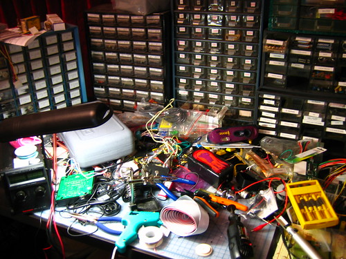
To be able to reliably use the OhMiBod for testing, I needed it in a package that I could easily access and switch out motors on, and that had a couple of basic test functions so I could at least tell if the batteries were working without having to swap caps or have music on. I also wanted a pass-thru audio jack so I didn't have to keep track of where I put the audio splitter, because, well, I could clean up that mess, but it's almost got this "Jackson Pollock of Electronics" kinda structure going on, and I really wouldn't want to lose that inertia when I could possibly sell that for millions some day.
Therefore, the goals:
- Put OhMiBod in a package where I won't keep losing the damn circuit board
- Add Audio Pass-thru
- Add Battery Test/"Always On" Function
- Add Switch
- Add 2.5mm Jack for Modularity
With these goals in mind, I run the half mile down to Good Vibrations (have I mentioned how much I love living in the Bay Area yet? 'cause, really, I do), and start shopping for some new eggs, 'cause I burned most of mine out or can't find them (shut up). However, I find my new best friend in modding:
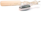
For $16ish, you get:
- A case with a ton of modding space in it (assuming you can work small)
- 2.5mm jack built in
- 2 AA Battery pack built in
- Nice knob based rheostat that you can take out and use elsewhere
So yeah, a smidge on the expensive side if you want to mass produce something, but otherwise awesome! With the Atmel ATTiny25/45/85 series, you could easily fit a chip in this capable of doing USB communications using the USBTiny Firmware. But that's another project entirely. Expect to see more of these around Slashdong in the future though, and if anyone from GoodVibes is reading, please send me a bunch of these for free. Kthx.
Back to modding.
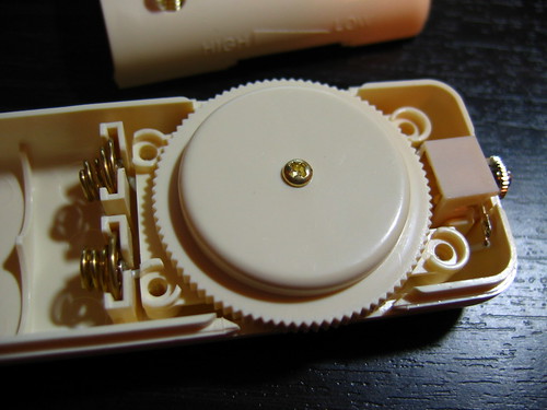
Here's what the vibe looks like before you take out the Rheostat. 4 screws gets the whole thing apart, and the rheostat lifts right out.
Quick reminder of what the OhMiBod board looks like:
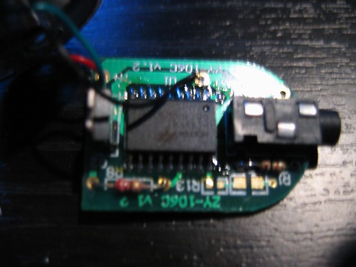
Black is POW-, Green is M-, Red is M+, and that little via with nothing in it above the audio jack is POW+.
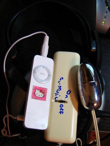
(Then there's a bunch of steps) and the mod is done!
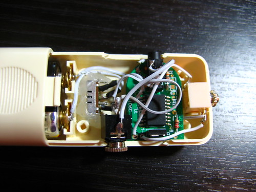
Quick description: switch is wired to control ground. +3v comes from batteries and goes to the OhMiBod board, which has a direct line to M+. M- on the board is controlled by the uC pulling the transistor to ground. The switch decides whether M+ routes through the transistor/M- path or goes directly through the motor (always on, no real current control or anything 'cause I don't plan on using this mode other than to test if my batteries work). Audio passthru is just wires soldered to the metal on the top of the audio jack to the corresponding pins on the 3.5mm jack.
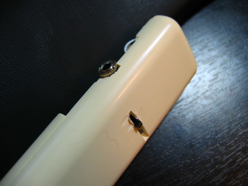
Case required a bit of Dremeling to get the 3.5mm input/output jacks to fit, and I cut a rather messy hole in the top for a 3 position switch. And, well, that's it! Nothing to interesting, but I feel productive nonetheless. Off to start working on that software now.
