SeXBox Version 4 - The defeat of the Pink Sparkly Buttplug of Doom
by qDot and LGM
9 Months and 1 IC Later
Remember the SexBox? Yeah, that xbox controller thingy that got this
little pervfest off the ground? Well, even though we haven't posted
about it in months, we certainly haven't forgotten about it. We've
just slowly been adding to it, and in the process, breaking 3 Xbox
controllers.
With that, the total research expenditure for Slashdong is now
somewhere around $80. Man, this page is gonna fuckin' break me.
Now, breaking stuff can be fun sometimes. I certainly enjoy it.
However, I like breaking stuff that is either cheap, or not mine. The
graveyard of Xbox controllers I have sitting next to my desk fall in
neither of those catagories. On each of their gravestones, there is a
picture to remind them the cause they died for.
BUTTPLUG! BUTT PLUG! BUTT! PLUG!
This is the Pink Sparkly ButtPlug. OF DOOM.

Why of Doom? Simple. Where all of our other vibrator eggs could run
quite nicely at the 2.5w (5v @ 500mA) supplied by USB, the Buttplug
ate controllers for lunch. It can easily pull 750+mA in current.
Attaching it to a SexBox v2 and setting it at sustained top speed, and
BOOM, no more feedback motor port on that controller. Even though I
realized what the problem was after burning out the first controller,
crossed wires and stupidity lent to the deaths of two more
controllers.
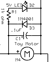
The SexBox v2 wasn't exactly complicated. In fact, here's the circuit
diagram for it.
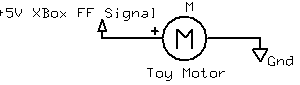
Yeah, see? Power source to DC motor. That's it. Woo.
Now that we're out of the "OMG LOOK WHAT I CAN DO!" stage of
development, we've actually got some goals we'd like to achieve with
this version. Specifically:
- Have FF motors in controller work along with External Toy Motors
- Be able to support up to 1A sustained/2A peak current through the
Toy Motors (just in case)
- External power supply for toys
With those goals in mind, let's get to work.
Parts List and Basic Explanation
Parts List:
For Controller/Motor Hookup:
- 1 - Video Game Controller
- We use Microsoft XBox S Controllers, and our voltages are based off
of those. If you want to use something else, we've generally found
that the internal circuit setup is the same, but the voltages can
differ greatly. If you know what you're doing, feel free to use the
controller of your choice and make the necessary modifications.
Otherwise, just do what we do.* 4 - Mono or Stereo Headphone Jacks
- 4 - Mono 3/32" Mini Audio Jacks
- 2 - Mono or Stereo Headphone Patch Cables
- 1 - 4 AA Battery Case (Or Equivilent Setup)
- 4 - AA Batteries
- 1 or 2 - Toys with 3/32" Mini Audio Jack Connectors
For the Motor Circuit:
- 3 - .1uF Polarized Capicitors
- 2 - 1N4001 Diodes
- 2 - 5V LEDs
- 2 - 1k Ohm Resistors
- 1 - Switch, rated to at least 2A
- 1 - LM7805 5v Regulator
- 1 - Texas Instruments SN754410 Motor Driver
- 1 - Something to put the circuit on (Breadboard, small PCB board, etc...)
Obviously, there's a LOT more going on here than in the previous
articles, because this time we're going to actually try to look like
we know what we're doing, versus just slapping something together so
we'll get hits. Though I'm certainly going to miss that method of
content creation, it takes a hell of a lot less time.
Treating the whole circuit part of this as a magic box of dreams and
wonders, construction of the SexBox v4 is much similar to the earlier
versions. The stereo headphone jacks will be placed in the Xbox
Controller, soldered to the Force Feedback pads on the opposite side
of the motor connections. We'll run the stereo headphone patch cable
from the controller to the magic box of fairy dust and love. Inside
there, the PWM signals from the controller are massaged and pedacured
through a spa of scantily-clad nymphs, which sends them out the 3/32"
jacks ready to work with whatever basic vibrating sex toy you choose.
That's the easy part. Most of the rest of this article will be spent
explaining away all of the aforementioned magic in stark, boring
engineering terms. So get your learning belts on, kids, 'cause it's
gonna be a long ride.
So... Many... Lines...
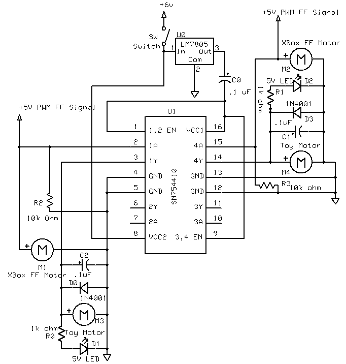
Ok, so now, I'm going to show you the schematic for the SexBox v4.
It's big. Much bigger than version 2. But don't get freaked out, we'll
be explaining each and every part of it.
unzip
(Click image for much bigger, more readable version)
See? I told you it was big. Now then, I didn't just get it out to give
it some air... [/creepy Requiem for the Dream reference]
To make life a little easier, we're going to divide the circuit into 4
parts and explain each of them, then tie it all back together in the
end:
- The main power and chip drive circuits
- The Xbox control tomotor driver circuits
- What happens in the motor driver
- ToyOutput
Powering the System
It all starts at the battery pack. From the spec sheet of the motor
driver, we know we need to get a steady 5v (actually, 4.5v to 5.5v,
but it's nice to have a linear, stable supply line) to the chip, and
anywhere between 4v and 36v to the motors. As stated in the parts
list, we're planning on using 4 AA batteries. At 1.5v per battery,
simple math that you should have either already done in your head by
now or else should stop reading about hooking electronic things to
sensitive parts of your body tells us that we're supplying 6v to the
system. Obviously, 6v is more than the 5.5v max, and if we ship that
much potential through the logic line, there's a good chance we'll
push the chip in the undocumented "not working" feature state. This is
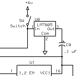
a job for a 7805 regulator!
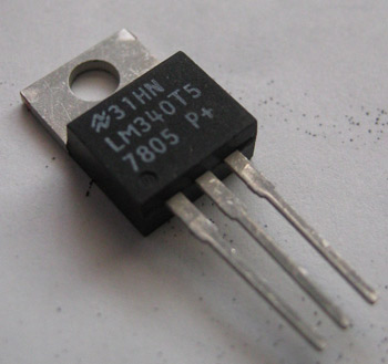
7805 Regulator Spec Sheet
The 7805 regulator is pretty simple. It takes up to 35v at .5A and
turns it into 5v. That's pretty much it. Since we're only sending
logic level current through the chip (around .013A), we don't have to
worry about strapping a heatsink to the regulator.
While the 7805 is good for making sure we're at 5v, it's not the most
stable 5v line in the world. Therefore, we put a .1 microfarad
capacitor in series with the regulator output, leading to the VCC1 pin
on the chip. The capacitor will act as a stablizer, meaning we'll get
a decently smooth 5v flow to the chip.
Since the power line to the chip is now figured out, let's work on the
line to the motors, or VCC2 on the diagram. All we do is bypass the
regulator and hook the battery pack straight to the VCC2 line,
supplying 6v to the motor line. Note, the motors themselves will only
get 4.7v, as there's a 1.3v voltage drop over through the transistor
network in the chip. We'll explain more about this later.
The Xbox Control to Motor Driver Circuits
Now that we've got power set up to the chip, it's time to hook up our
trigger lines. What we'll be doing here is essentially similar to the
first three versions of the SeXBox, in that we're using the signals
initially meant for the force feedback motors to run our own motors.
The major difference is that this time, instead of completely
unhooking the force feedback motors, we leave them intact in the
controller, and simply run taps to the lines to pull them to the logic
level enable pins on the motor driver chip. This change is what saves
us from blowing up controllers.
For those of you that remember how current draw works, you'll realize
that we're now pulling 2 different currents in parallel. I'm honestly
not sure what the Xbox controller motors are rated to, but we know
that, assuming we have the proper resistor in parallel with the
activation pin, we'll only be pull a very tiny amount of current along
with what's going to the motor. This way, we won't overload the
controller motor ports, and nothing will get broken.
Of course, there's the issue of what happens once we activate the
enable pin. This is where the explanation of the motor driver comes
in.
Inside The Motor Driver
Now we get to the new stuff, mainly, transistor pairs. First off,
you'll probably want to know what a transistor is though.
I could go ahead and explain what a transistor is and how it works
here, but why do that when there's a million other pages on the net
that do it,
like this one. But, if
you really want to know... Basically, a transistor allows you to vary
the amount of current going through the transistor by applying
different voltages to it. The ratio of the amount of current change in
relation to the amount of voltage change is known as the gain value
for the transistor.
Image taken from TechnologyStudent.com
To get power to the motors, we are using what is known as an H-Bridge,
which implements a Darlington Transistor Pair. This type of transistor
setup allows us a VERY high amount of gain, meaning that using a very
small amount of power from the motor tap, we can send a massive amount
of current to the output pins of the motor driver in order to make
things vibrate. The TI SN754410 motor driver is rated at 1A max
sustained, 2A max peak. In using this with video games, you really
don't see too much sustained, full on power, so we should be fine.
Assuming this is used to work with teledildonics software, it might be
wise to test your toys to see the amount of power they draw, just in
case. Either way, the motor drivers are stackable, meaning that you
can just add another chip in parallel and double the available output
current. Of course, you'll also want to think about heatsinks if
you're going in that direction, but since we're not, you can think
about that on your own time.
SN754410 Spec Sheet
So, as I said, this is the Texas Instruments SN754410 Quadruple Half-H
Motor Driver. In English, that's gonna take a least a paragraph to
explain. An H-Bridge is basically a circuit that simply lets you
control motor direction through a circuit that looks something like an
H.
Picture taken from ecircuitcenter.com
As you can see, when the Q1/Q3 transistors are activated (just think
of them like a switch for the moment), the current flows one way. If
Q2/Q4 were activated, current would flow the other way.
Each one of the pin pairs on the chip is a "Half H-Bridge", meaning
it's only one of the pairs shown above.
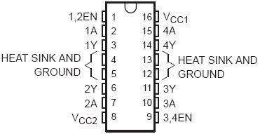
The combination of 1/2EN, 1A and 1Y would basically equal one
H-Bridge. If power is applied to the 1/2EN and 1A pins, then enough
power comes out the 1Y pin to make the motor go. So, you could hook 1Y
and 2Y to the same motor, have opposite directions of flow through
each, and be able to turn the motor either forward or backward,
controlling a total of 2 motors from the chip. However, since all
we're worried about is vibration, flow direction doesn't matter. It
can go forward or backward, it's still going to vibrate.
All we're doing with the chip is applying power to the 1A and 4A pins,
for varying, very short amounts of time. This varies the amount of
power that makes it to the motor, controlling motor speed.
Let's recap. We've now got power going to the chip and available to
the motors. We've got the XBox controller wired into the circuit so
that it will activate the motors as well as run its own force feedback
motors. Finally, we've now got the motor driver dealing with changing
our very small signal into a very large signal. We're now ready to
make our motors go!
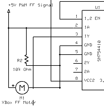
Vibration, Noise Reduction, and Blinky Lights
So now we've got power coming out of the end of a wire, let's do
something with it!
As you can see, there's an absolute ton of shit going on here. In the
last versions, we simply hooked up the motor to the power supply and
went on our merry way, completely oblivious to noise.
Noise can basically be considered to be any signal on the line that we
don't want there. This is usually caused by some sort of interference.
This interference can do very wacky, very "undefined" things to our
circuit (including completely blowing up our chips, as integrated
circuits can be VERY sensitive), generally making our lives hell until
we fix it. Therefore, even though it might not be much of an issue, we
put safety measures in place to make sure we won't ever need to worry
about it.
In this case, we're worried about Back Electromotive Force (or Back
EMF). When we spin up the motor using a voltage, the field in the
motor itself creates a voltage and tries to send it back across the
line. This causes noise. To reduce this noise, we create something
known as a snubber. In this case, it's a R/C (Rectifier/Capacitor)
network that makes sure voltage only flows in the correct direction.
We've also added in an LED, just for the sake of showing us status.
Even if we don't have a motor on the circuit, we'll get power through
the LED, letting us know that the circuit is working. Not to mention,
you can never have enough little blinky lights.
Finally, the motor! The motor is connected in through a 3/32" jack on
the circuit, and well, that's it. We're done. We're exactly where we
ended with version 2, but now a hell of a lot safer. No more blown
controllers! The Buttplug of Doom is tamed!
Controller and Project Box Construction
Now that you've got the circuit together, it's time to put the
connectors together so we can get this thing running off an XBox
Controller.
The process on the controller side is exactly the same as the SexBox
Version 2, with two small differences.
- Don't disconnect and remove the motors. Just leave them in.
- Use stereo headphone jacks in the controller. Since these jacks
won't fit the normal 3/32" sex toy plugs, you won't be tempted to
plug a toy right in and ruin a controller. Instead, use the 3/32"
plugs on the output end of the motor driver.
So, our connection chain should look like:
- Xbox or PC to Xbox Controller (Duh)
- XBox Motor Pads to Stereo Headphone Jacks (Inside Controller)
- Stereo Headphone Jacks to Patch Cable
- Patch Cable to Stereo Headphone Jack (On Circuit)
- Stereo Headphone Jack to Motor Trigger Pin (1A/4A on chip diagram)
- Motor Output Pin (1Y/4Y) to 3/32" Mono Jack
- 3/32" Mono Jack to Sex Toy
As you can imagine, this is a lot of wires. However, just learn to
find wires hot, and this turns into one seriously sexy setup.
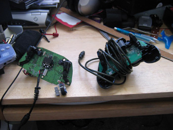
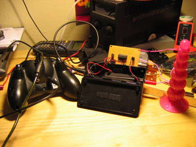
The following is how I decided to set up the project box and
connections for this project. This is by no means a recommendation to
do things this way, because it ended up being somewhat unwieldy, but
it'll give you an idea of how the end product can possibly look.
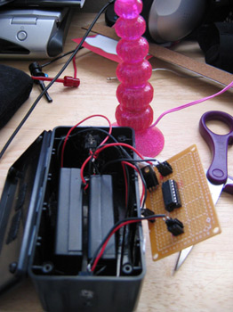
The project box I bought is just one I found at radio shack. It
barely had enough enough room to house the two 2xAA battery cases I
bought (wired in series to create the 6v supply) plus the circuit
board. I drilled two holes in each side, one side for stereo jack and
switch, the other for the output plug. (Note that the version shown in
the picture only accomidates one toy. Technically, you could support
up to 4 toys on one chip, triggering them by splitting the activation
lines.) I used header pin connectors to connect the jacks to the
circuit, so things could be easily taken apart and shown off. However,
I would recommend direct connecting the jacks into the circuit unless
you have some good reason not to.
Putting it all together
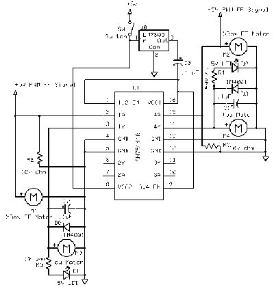
Ok, now that we've put around 1000 words to our picture, let's take a
look at the schematic again.
(Once again, click image for much bigger, more readable version)
Make more sense now? Good. 'cause I'm not explaining it again.
So, what should it look like in assembled, finished, usable form?
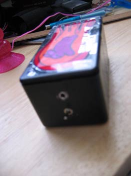
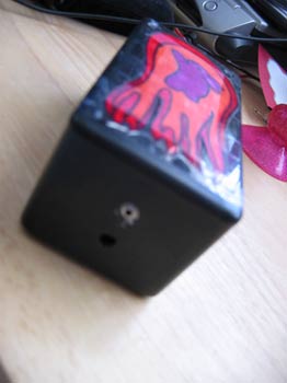
Please note, the flaming bunny art is a requirement. A SeXBox v4
without a flaming bunny is just not a SeXBox v4.
What's next
I am so god damn sick of XBox controllers now that I could scream, so
it's time to say goodbye to our namesake, and start working with our
own microcontroller. In the next version, we're goin' the way of the
uC, and making ourselves something nice, modular, and truly
teledildonics worthy. We may do a .5 revision of this one just to take
a shot at putting in a function generator as well as some other
basics, but the next major revision, damn, it's gonna be hot.
Hopefully it won't take 8 months like this one did, either.